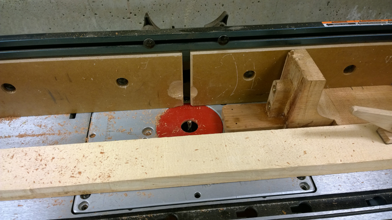
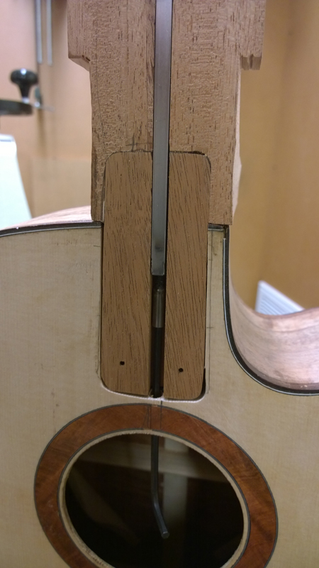
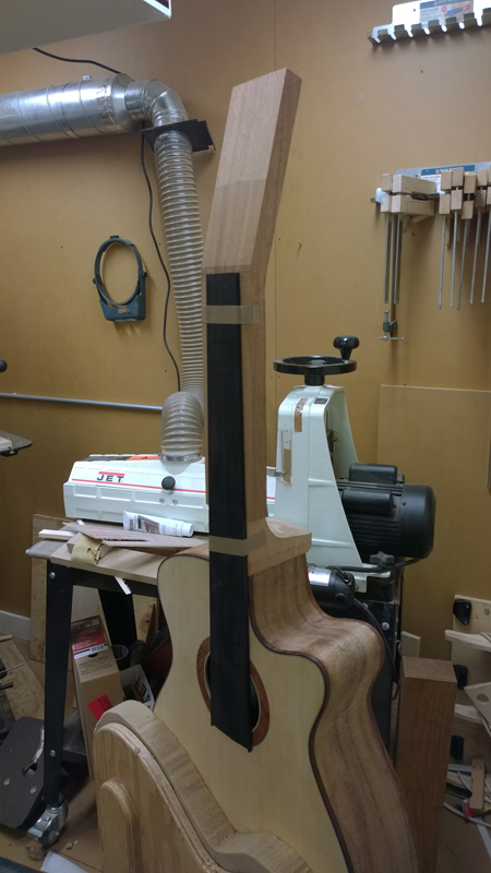
Build thread for first Gore SS from the plans in the book.
-
- Blackwood
- Posts: 552
- Joined: Mon Jan 21, 2013 2:59 am
- Location: Seattle
- Contact:
Re: Build thread for first Gore SS from the plans in the boo
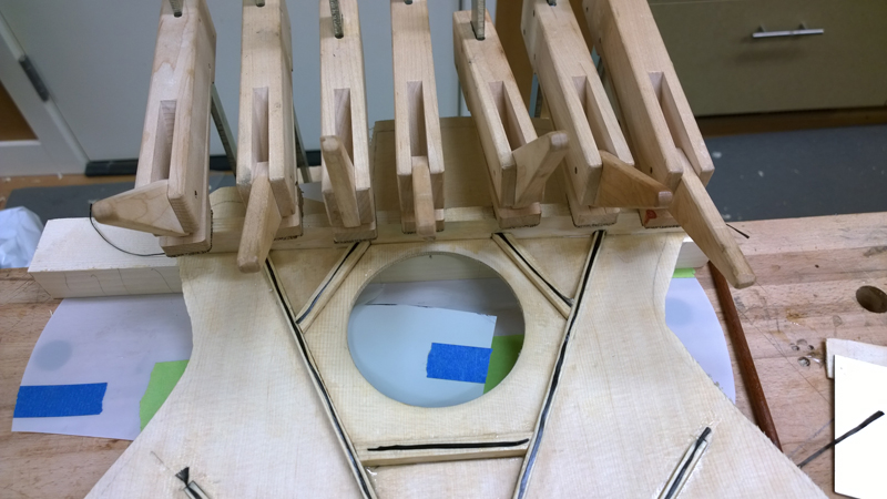
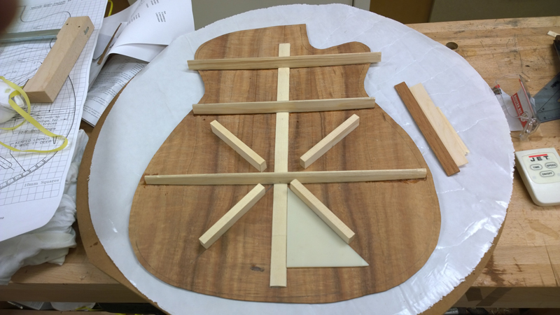
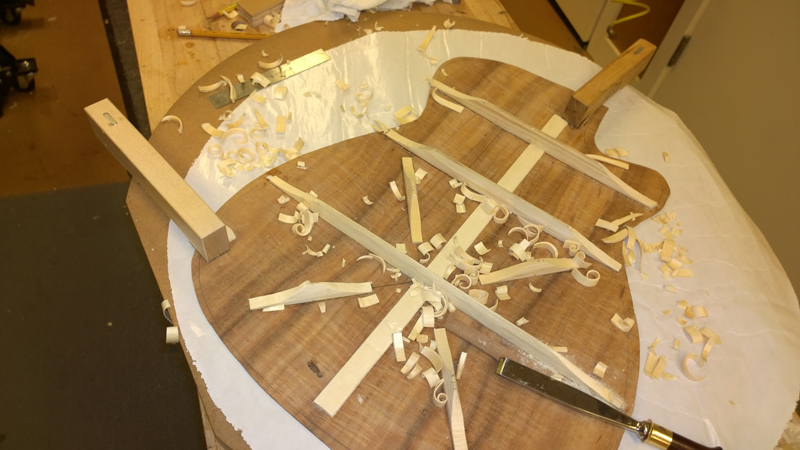
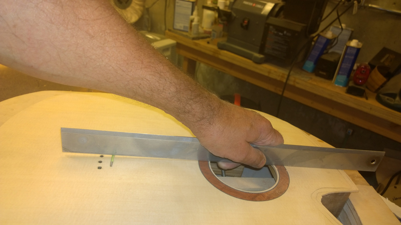
I carved out a caul for the upper transverse brace with a cabinet scraper. The caul was 400mm long and was dished to about 1.4 mm flattened in the fret board extension area. It seemed like around 40' radius with the fret board area flattened. I planed in the profile to the brace and touched it up on the caul. Also I laid down some carbon fiber before epoxying the brace to the top.
-
- Blackwood
- Posts: 552
- Joined: Mon Jan 21, 2013 2:59 am
- Location: Seattle
- Contact:
Re: Build thread for first Gore SS from the plans in the boo
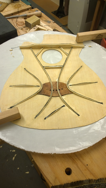
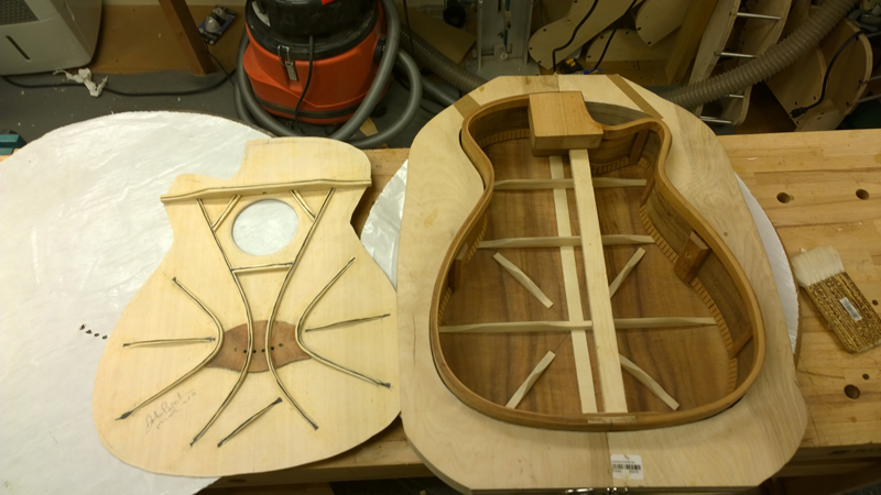
Here is the completed top bracing, now on to building a guitar to use it.
- Trevor Gore
- Blackwood
- Posts: 1629
- Joined: Mon Jun 20, 2011 8:11 pm
Re: Build thread for first Gore SS from the plans in the boo
That looks familiar!
Fine classical and steel string guitars
Trevor Gore, Luthier. Australian hand made acoustic guitars, classical guitars; custom guitar design and build; guitar design instruction.
- Nick Royle
- Wandoo
- Posts: 16
- Joined: Sun Oct 06, 2013 1:34 am
- Location: London, England
Re: Build thread for first Gore SS from the plans in the boo
Hi John, My first post on the ANZLF can be congratulating you on your progress so far! Great work!
I'm looking forward to trying this out myself.
-
- Blackwood
- Posts: 552
- Joined: Mon Jan 21, 2013 2:59 am
- Location: Seattle
- Contact:
Re: Build thread for first Gore SS from the plans in the boo
Thanks Nick, I look forward to seeing your work.
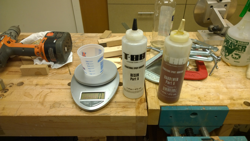
Trevor, I still need some practice with the epoxy I think I got it on nearly everything. The braces do seemed glued down and the top feels like a braced top.
- Trevor Gore
- Blackwood
- Posts: 1629
- Joined: Mon Jun 20, 2011 8:11 pm
Re: Build thread for first Gore SS from the plans in the boo
Hi John. I came at this type of work with epoxy from a fair amount of boat building experience, so never found it too problematic. Experience certainly counts, though. Things that help are the right size/stiffness of brush so you can paint the epoxy on accurately, and good access to the work. I have my (moveable) go-bar deck on a "peninsula" bench that gives me access from 3 sides and I can also spin the whole deck if I want. So I can can always work from the most comfortable/convenient angle. It's often over 30C in my workshop (windows three sides), so I find I have to work really fast before a mix goes off, but the good lighting, because of the windows, also helps.
On the next one ( ) try to "fishtail" the ends of the CF some more, which avoids a hard spot where the CF stops and so helps guard against accidental detachments should the guitar get a knock in the wrong place. Leave the fishtailing until last, but put a drop of epoxy on the area early in the piece. The extra epoxy will help the CF tow float out and then just lift off the excess with a dry* brush.
* Just squeeze the brush out with a paper towel.
Fine classical and steel string guitars
Trevor Gore, Luthier. Australian hand made acoustic guitars, classical guitars; custom guitar design and build; guitar design instruction.
-
- Blackwood
- Posts: 552
- Joined: Mon Jan 21, 2013 2:59 am
- Location: Seattle
- Contact:
Re: Build thread for first Gore SS from the plans in the boo
Thank you Trevor,
Thanks for the tip on the tails. Having the excess epoxy to float the fishtail will help. I am sure I will get cleaner with experience.
I have all the templates, dishes and molds for this design, so I will make more. I will also try a classical guitar with falcate braces as well. I am considering this guitar a learning exercise; I plan on keeping it for myself. Lots of new features for me ahead: side weights, bolt on bolt off neck, active back and compensated nut.
The last few days I had to keep peace in the household come up out of the shop and install a poly-carbonate roof on our all steel pergola in my wife's garden. She is a landscape designer by trade, if I am not careful she will have me working full time.
- Trevor Gore
- Blackwood
- Posts: 1629
- Joined: Mon Jun 20, 2011 8:11 pm
Re: Build thread for first Gore SS from the plans in the boo
Just box in the sides as well and call it a workshop.johnparchem wrote:The last few days I had to keep peace in the household come up out of the shop and install a poly-carbonate roof on our all steel pergola in my wife's garden.
She'll never know!
Fine classical and steel string guitars
Trevor Gore, Luthier. Australian hand made acoustic guitars, classical guitars; custom guitar design and build; guitar design instruction.
-
- Blackwood
- Posts: 552
- Joined: Mon Jan 21, 2013 2:59 am
- Location: Seattle
- Contact:
Re: Build thread for first Gore SS from the plans in the boo
It would be bigger than my shop!Trevor Gore wrote:Just box in the sides as well and call it a workshop.johnparchem wrote:The last few days I had to keep peace in the household come up out of the shop and install a poly-carbonate roof on our all steel pergola in my wife's garden.
She'll never know!
- Nick
- Blackwood
- Posts: 3639
- Joined: Thu Feb 26, 2009 11:20 am
- Location: Christchurch, New Zealand
- Contact:
Re: Build thread for first Gore SS from the plans in the boo
Tell her they are 'removable wind breaks' John, she'll never know until she goes to plant a shrub and there's a go-bar deck in the way (good to see you can't see any neighbours in that shot too! Would love to live surrounded by nature.)
Following this build with interest by the way, thanks for sharing your Falcate experiences and snags with those of us that have yet to dip our toes into Trevor's methodology pool. It's nice to see completed tops but also great to hear that things can and do go wrong and how you've resolved them, Trevor makes it look so easy .
"Jesus Loves You."
Nice to hear in church but not in a Mexican prison.
-
- Blackwood
- Posts: 552
- Joined: Mon Jan 21, 2013 2:59 am
- Location: Seattle
- Contact:
Re: Build thread for first Gore SS from the plans in the boo
Thanks Nick!
I will get to see pictures of your carbon fiber lattice braced guitar. It will be fun positioning the lattice braces on all the carbon strips, and keeping the carbon under them while you are clamping the lattice!
btw, every plant you see she planted. It was just lawn when we bought the property.
I will get to see pictures of your carbon fiber lattice braced guitar. It will be fun positioning the lattice braces on all the carbon strips, and keeping the carbon under them while you are clamping the lattice!
btw, every plant you see she planted. It was just lawn when we bought the property.
-
- Blackwood
- Posts: 552
- Joined: Mon Jan 21, 2013 2:59 am
- Location: Seattle
- Contact:
Re: Build thread for first Gore SS from the plans in the boo
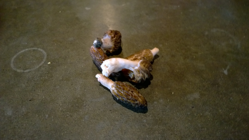
I did find one reward to working outside on the pergola, a small batch of morel mushrooms for a tasty snack.
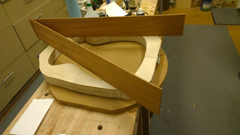
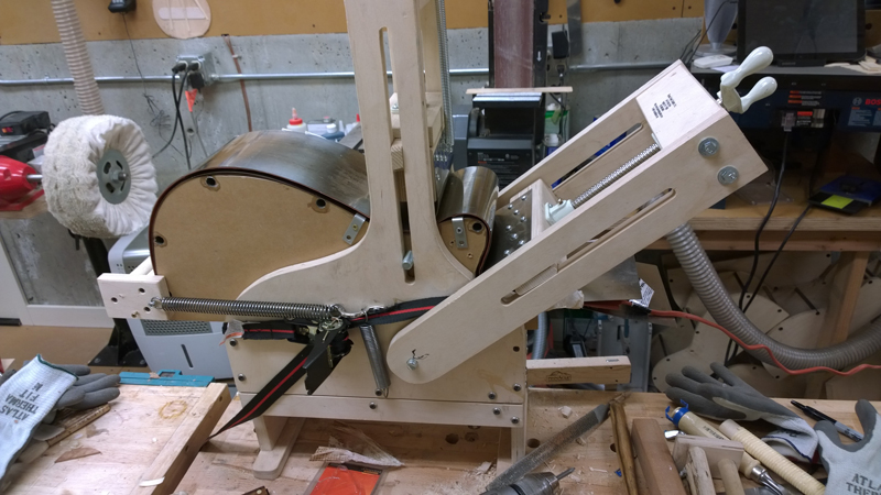
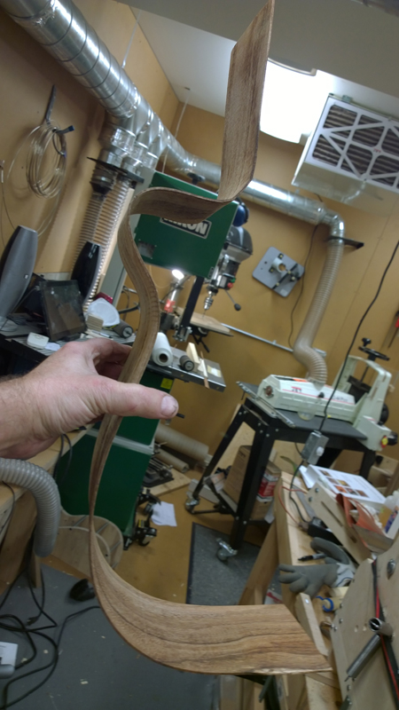
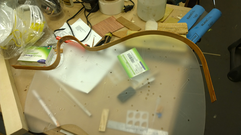
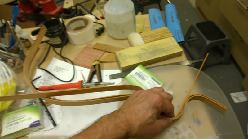
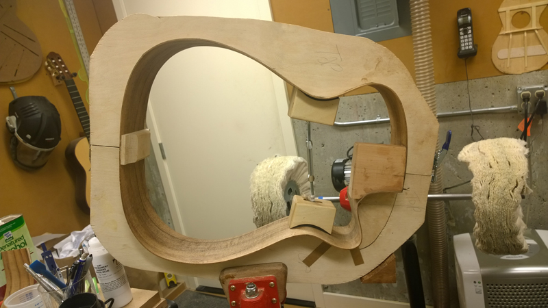
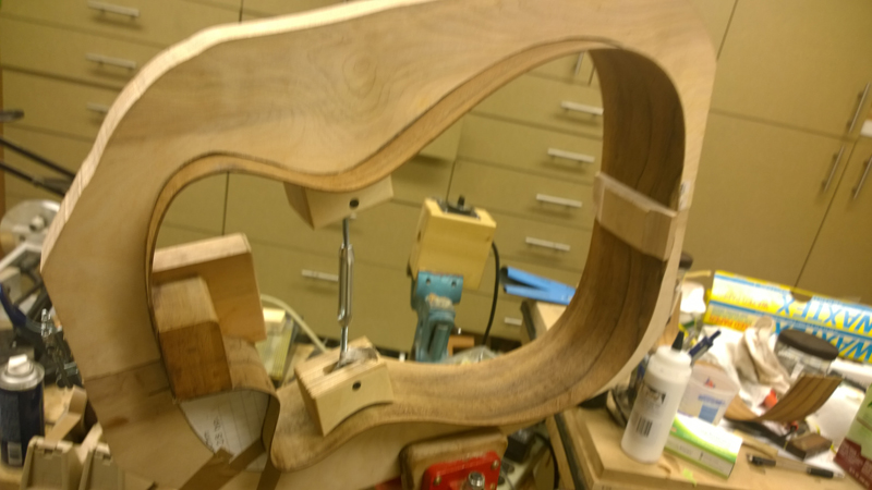
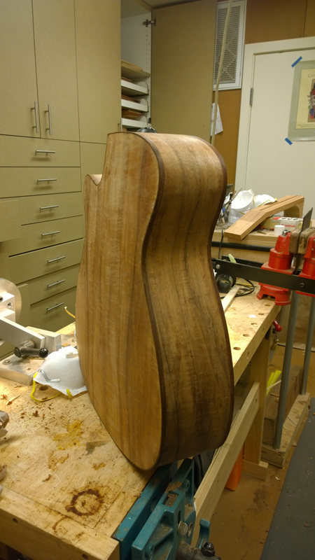
I finally made it back in the shop Friday and got the sides bent. There is a pretty tight bend for the cutaway.
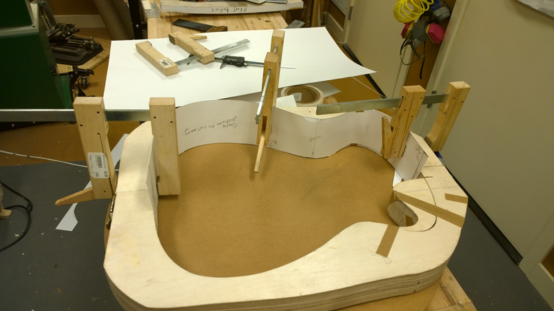
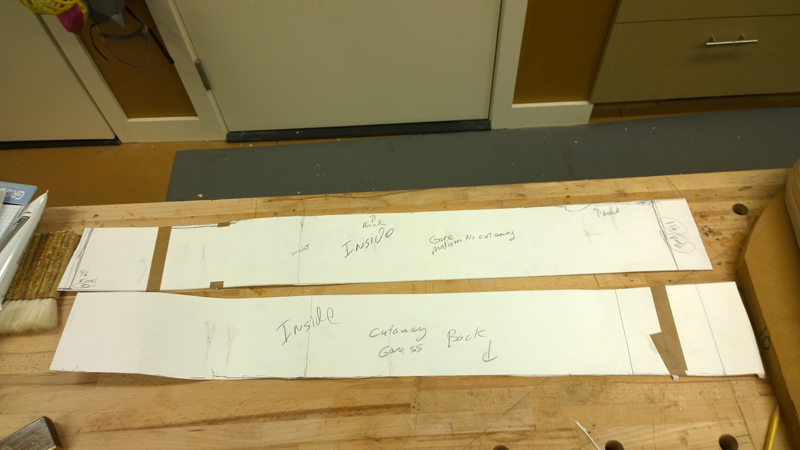
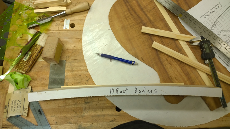
First I had a bit of prep work. I used a 10' radius dish I am using for the back radius to make an accurate template of the profiled sides. I put a strip of poster board into the mold on top of the radius dish and used a pencil in a small bit of wood to trace the curve of the radius board on to the poster board. from the neck and tail side of the curve, I measured up the depth of the body, plus a 10 mm, drew a straight line for the top and cut out the profiles. I leave the top flat has I will use it as a reference when I am first setting the rims in the mold.
I cut out the side profiles and then used my drum sander to thickness both sides to 2.2 mm. I used a scraper to thin the cutoff side from above the waist to 1.9 mm so I would have a chance of bending them.
I took extra care was to keep track of the top and outside of each side so that I would not bend the asymmetrical sides for a left handed guitar. I must have checked this 10 times. I did once end up with a sides for a left handed harp ukulele.
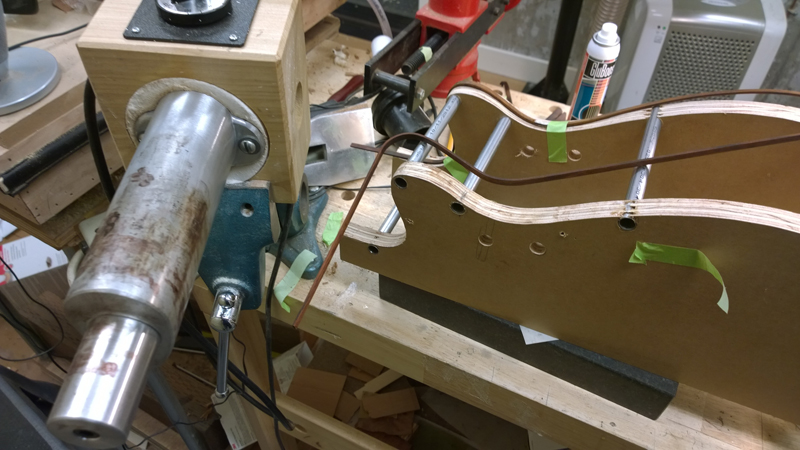
As the profile for this guitar has different proportions for the upper and lower bouts I found I had to drill a new set of holes in my bender to put the cutaway press in the correct space.
Also notice the band clamp. The last time I did a Florentine cutaway the spring back on the sides was scary. This time as I loosened the cutaway press I tightened the clamp holding down the lower sheet of spring steel.
.
.
All and all it tuned out ok. I had a bit of fibers tearing away on the inside. I used a bit of CA to fix.
-
- Blackwood
- Posts: 552
- Joined: Mon Jan 21, 2013 2:59 am
- Location: Seattle
- Contact:
Re: Build thread for first Gore SS from the plans in the boo
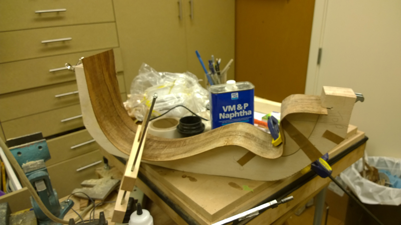
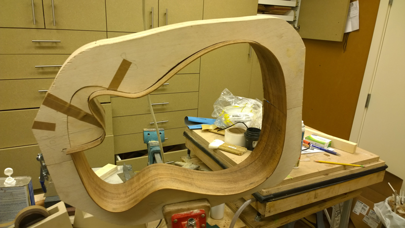
Amazingly, the guitar rims fits in the mold. I think I will find a very bendable wood for the bindings. The last one I did I used ebony, it only took 10 or so strips to bend 2 without cracking.
-
- Blackwood
- Posts: 552
- Joined: Mon Jan 21, 2013 2:59 am
- Location: Seattle
- Contact:
Re: Build thread for first Gore SS from the plans in the boo
I really should have been making the heel and tail blocks (they should have been finished a few chapters back) but I wanted to get a feel if I could pull off the laminated linings. I have a whole stack of practice sides that I bought once for bindings and linings. Included in that stack were an orphan Honduras Mahogany and a mahogany side. So I cut up and bent 3 2.2 mm thick strips of Honduran mahogany on my bending iron to laminate for the linings. The last strip sure was tight. I got better as I did them. I actually found that they bent better dry than wet. I have a mahogany side as well that I might try. Although I think these will work.
-
- Blackwood
- Posts: 552
- Joined: Mon Jan 21, 2013 2:59 am
- Location: Seattle
- Contact:
Re: Build thread for first Gore SS from the plans in the boo
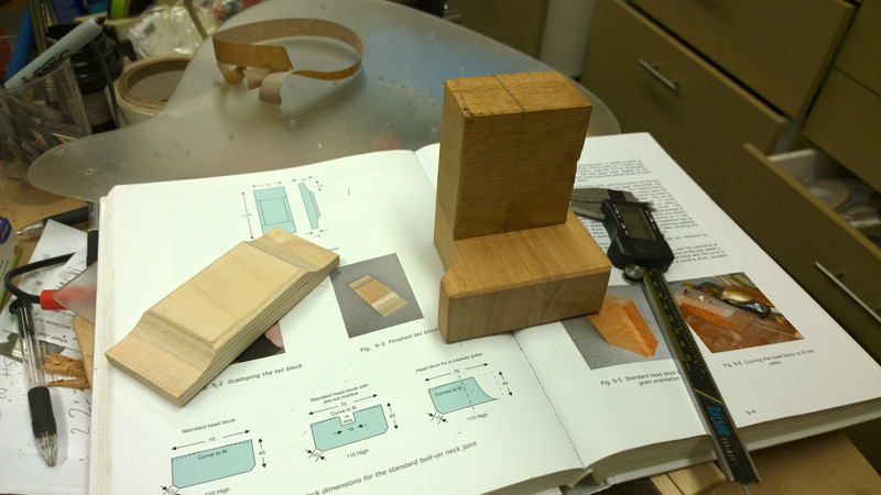
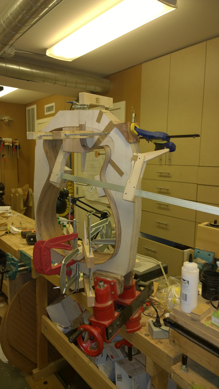
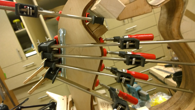
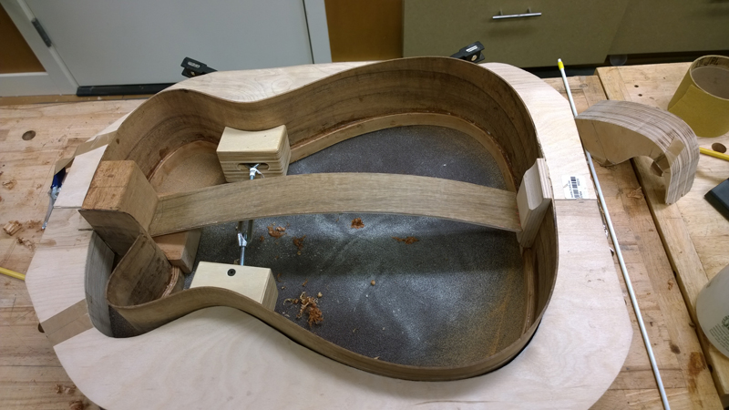
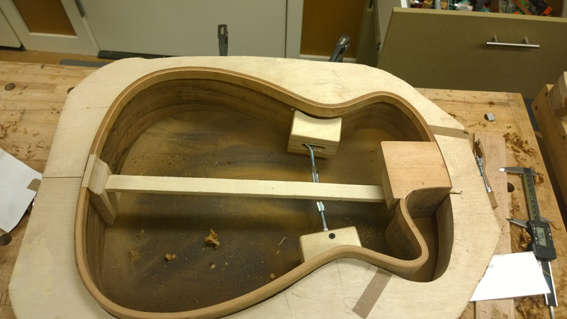
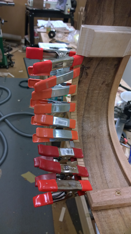
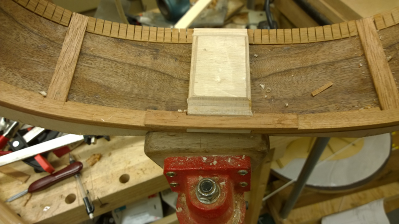
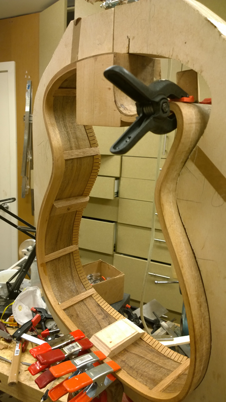
I made a bit of progress the last few days. This post will show my work to make the neck block for the bolt on bolt off neck joint and the tail block. The tail block is glued in with LMI glue and the neck block is currently clamped up while the structural epoxy I used is curing. More about the glue up further down the post.
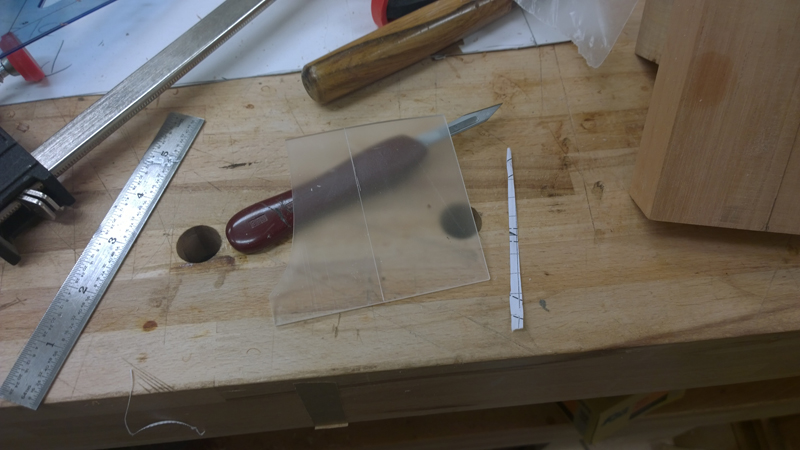
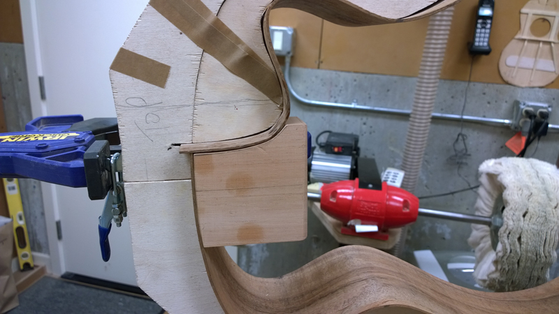
The bolt on bolt off neck block needs to support a neck extension that will be routed in to the neck block. Also the block needs to be profiled to match the Venetian cutway side. Here is a picture of the completed blocks.
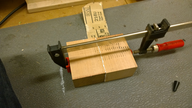
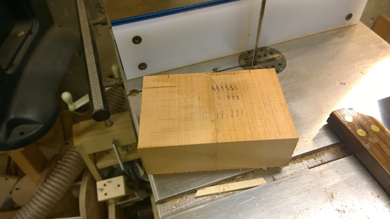
My first minor issue to make the neck block was to get a thick enough block of wood (I am using mahogany ) thick enough but with the a wide enough face to make the extension block. I have a lot of mahogany, but ultimately I needed to resaw and joint a thicker block.
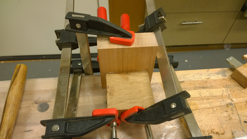
I glued the extension to a more typical sized neck block that would be used with a typical bolt on neck.
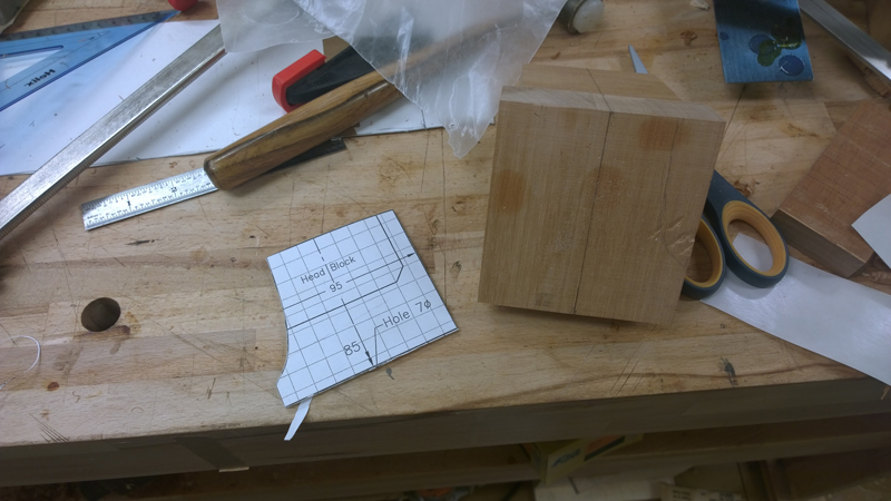
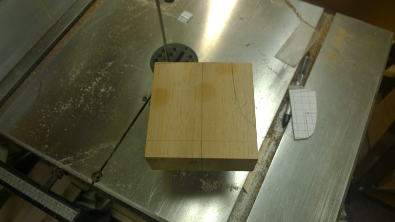
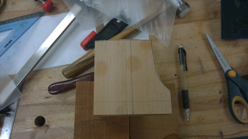
To get the correct profile on the block I made a template of the blocks face.
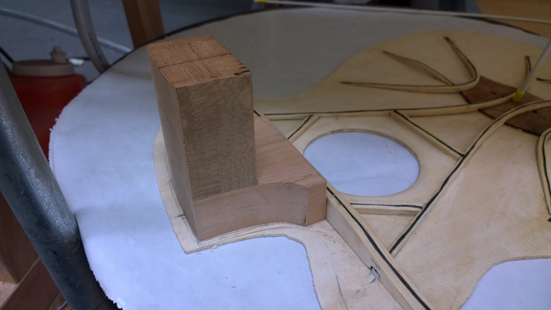
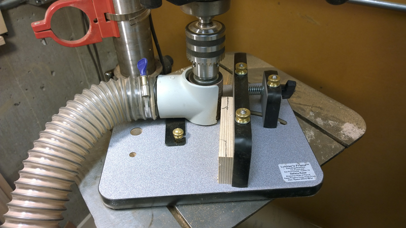
I transferred the profile to the glued on neck block and rough cut it on the band saw. I then also trimmed the block to fit the transverse brace. I do not have a picture but I cleaned up the neck block in a drum sander I had chucked in a drill press.
Pretty close fit!
The tail block is just birch plywood with wings sanded using my luthiers friend.
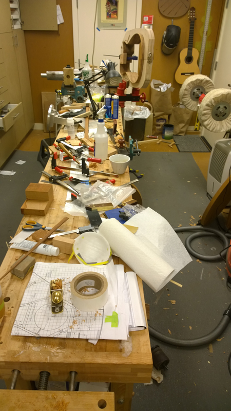
The work took a toll on my shop.
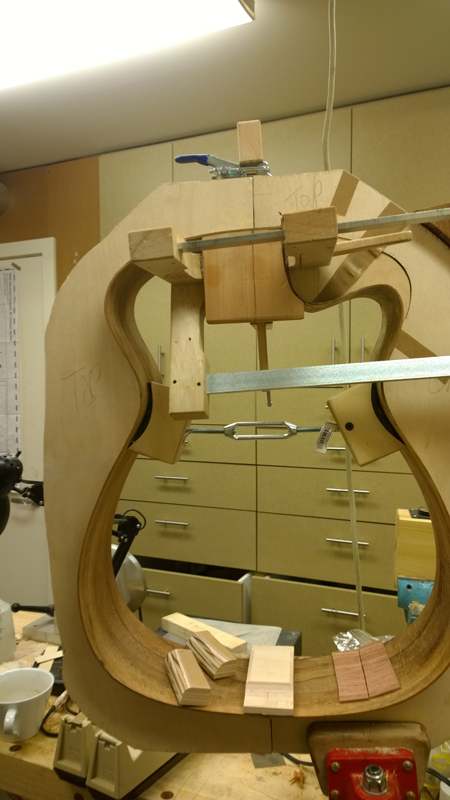
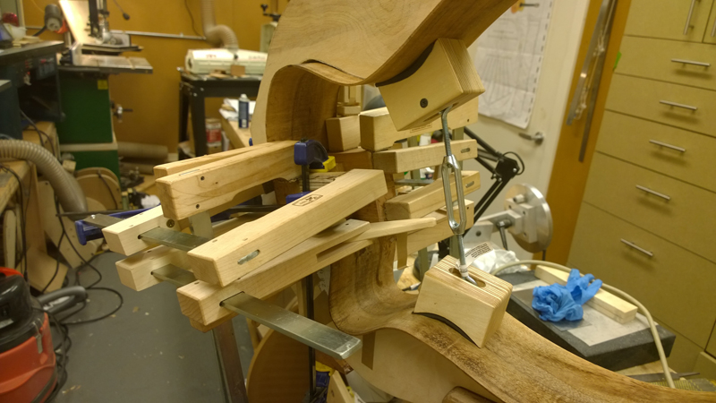
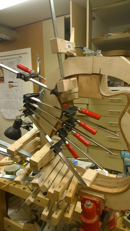
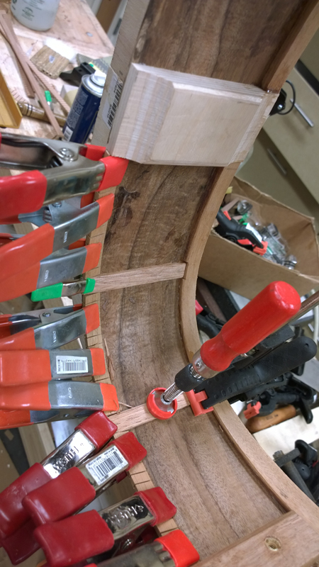
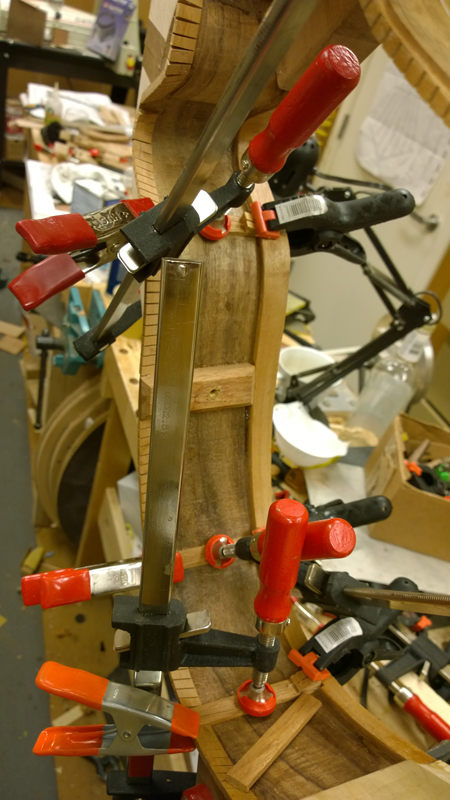
Bunches of clamps later I glued in the tail and am currently epoxying the nexk block on. My joint for the neck block was pretty tight and I probably could of just used LMI white glue. But it was such a complicated shape to clamp I though the add advantage of structural epoxy fill here or there would not hurt.
There were a lot of clamps used for the neck block
Also somewhere a long the line I bent the lines for the non-cutaway side. I did not have enough Honduran mahogany and used just mahogany instead for the two inside strips. It sure is a lot easier bending Honduran mahogany. I was sort of proud after the cutaway bindings. Now I know I still need practice.
-
- Blackwood
- Posts: 552
- Joined: Mon Jan 21, 2013 2:59 am
- Location: Seattle
- Contact:
Re: Build thread for first Gore SS from the plans in the boo
The epoxying of the neck block went OK. Everything seemed to be in the right place and glued down
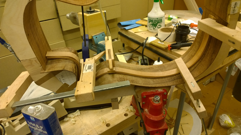
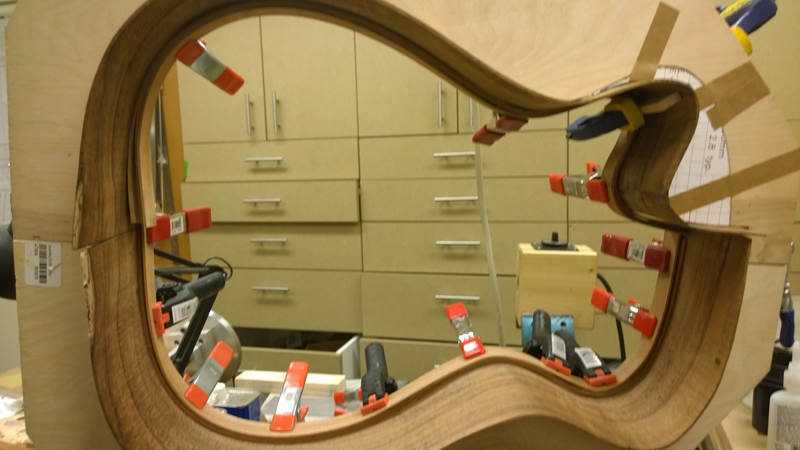
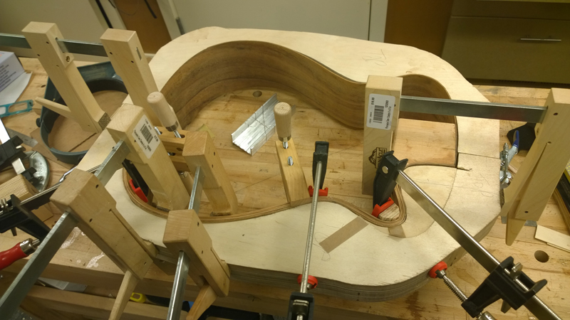
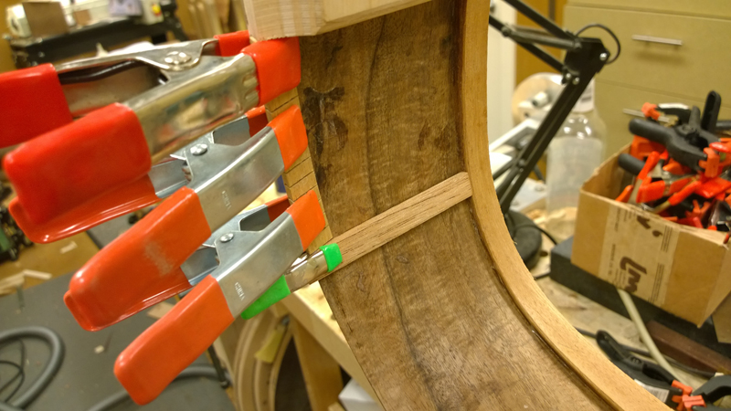
Not have a special form for gluing making laminated linings together and I decided, as suggested in the book to both glue the laminate together at the same time as gluing them to the rims. Before starting I knew that there going to be the need for a few clamps and as things slides around I would need some time to get everything clamped tight and the bindings at least close to level, I decided to use fish glue. It is great stuff but it likes to stay clamped for 12 hours.
In the first picture you can see that I made a caul for inside of the cutaway. As it was not perfectly bent some clamping force was required. In this picture if you look toward the center I used really cute 4" hand screw clamps to square up the stack of linings as I clamped along the stack.
Ultimatly I am glad I had the time with the fish glue as there was some jockeying of clamps before I was happy. I started with the cutaway side. the neck day I did the non cutaway side.
The glue up went well on both sides. The rims are really stiff with the linings installed. A noticeable difference from regular kerfed linings.
Using a block plane and my radius dishes I profiled the back and top rims. First the top, and then I measured the heieght I wanted at the center of the blocks and used my poster board rim profiles to draw a rough profile where the back rims would be. When I started my neck block was a bit over 10 mm long, so I actually took the body to the band saw to cut the back profile a bit closer.
Now I need to put the kerfed linings on the back rims, make and install the side reinforcement strips and make and install the side weight mount.
Re: Build thread for first Gore SS from the plans in the boo
Looking good John, When you insta'l the weight mounts check theyre in a spot thats easily accesible through the soundhole. On one build I stuck the mounts to far aft and screwing in the weights was a pain.
Martin
-
- Blackwood
- Posts: 552
- Joined: Mon Jan 21, 2013 2:59 am
- Location: Seattle
- Contact:
Re: Build thread for first Gore SS from the plans in the boo
Thanks, I put it down from the waist a bit. It is close to where Trevor had it in one of the pictures. I should be able to reach it no problems.kiwigeo wrote:Looking good John, When you insta'l the weight mounts check theyre in a spot thats easily accesible through the soundhole. On one build I stuck the mounts to far aft and screwing in the weights was a pain.
-
- Blackwood
- Posts: 552
- Joined: Mon Jan 21, 2013 2:59 am
- Location: Seattle
- Contact:
Re: Build thread for first Gore SS from the plans in the boo
I am getting close to finishing the rims. I still need to put the back in the radius dish again to clean up the kerfed linings and generally spend some quality time clean up the inside of the rims.
Today I added the kerfed linings for the back, installed the side splints and manufactured and glued on the mass support block. Somehow I did not take pictures making the mass support blocks but you will see them in the photos below. The mass support blocks will allowed me to add mass to sides to tune them a bit. More mass on the sides allows one to drop the top resonance frequency without little change to resonances. It is just a mahogany block with a nut in it. The book called out a t-nut, I used a brass insert (mainly cause I had them and did not have a t-nut. ), You can see it in the second picture.
As recommended I installed the kerfed linings in small strips and as you can see in the first and second picture I left room for the side splint. The side spint is inlet into the top linings and runs to the back. Ultimately they will be sanded with the back kerfed linings
In the next few pictures you can see a mass support block. I have one on both sides.
In this picture I am preparing to glue (following picture) a strap tying the kerfed top lining to the end block. It is used to avoid a ripple that sometimes shows on a top where the linings join the end block. I will blend the strap into the linings, once the glue sets.
-
- Blackwood
- Posts: 552
- Joined: Mon Jan 21, 2013 2:59 am
- Location: Seattle
- Contact:
Re: Build thread for first Gore SS from the plans in the boo
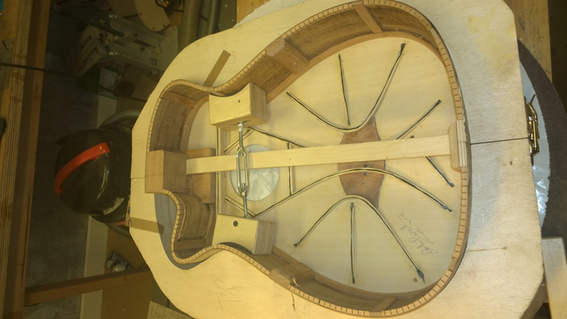
I have the body components finished and am in the process of cleaning things up and fitting the top and back on to the rims. This guitar is designed to have an active back so I thinned the back down a bit more than I normally would, used the plans 3 meter radius (well I used 10 feet) and used the plans active bracing pattern.
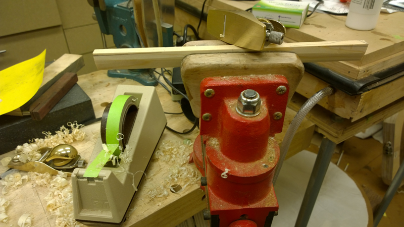
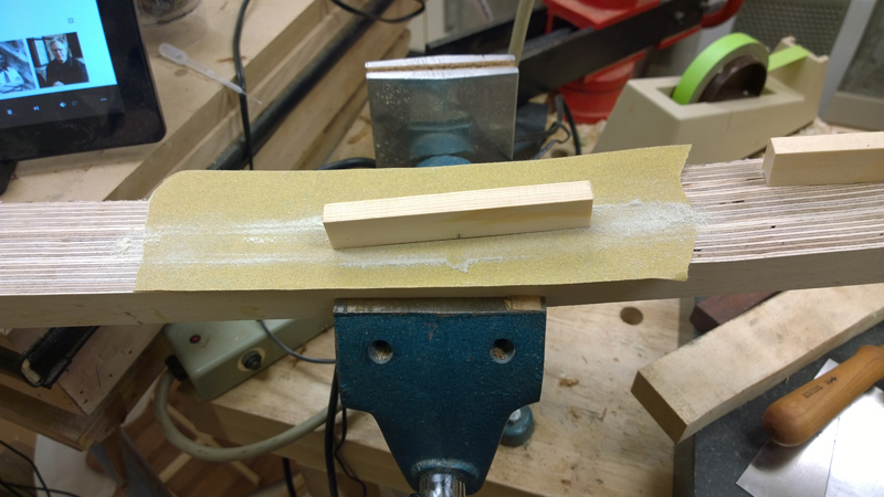
Bracing the back was pretty straight forward, the one change in my procedures was I could not use the 10 foot radius dish to radius the braces. I found it too had to not roll over the sides a bit. Instead I used the 10 foot radius board I made to first mark the radius for using a plane and I finished up the braces in the other side of the radius board.
The braces are all house shaped in their in profile. The book had a method of using a 22.5 degree router bit to shape the brace stock. I bought the bit but I found the process a little scary, so I used a chisel and a small plane to shape the braces.
Also the live back plan has a set of radial braces in the lower bout. I made a 30 degree square to set the brace location.
A bit of chisel work shaped the braces
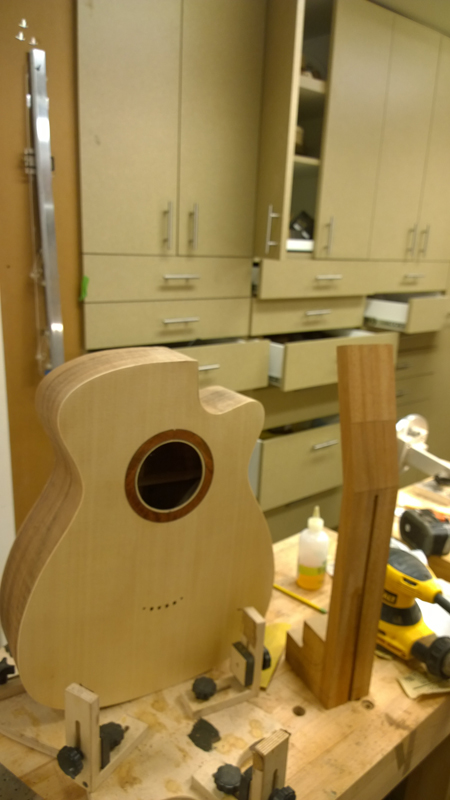
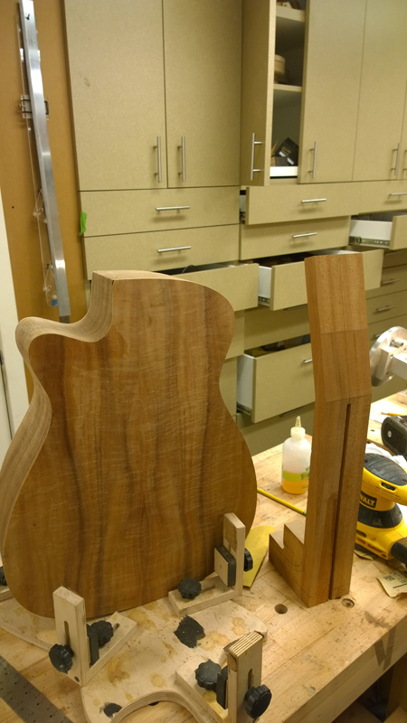
After a little bit of clean up I had the completed rims, top and back.
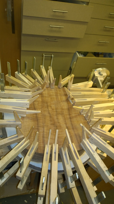
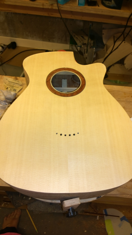
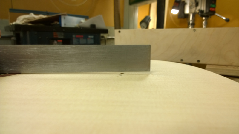
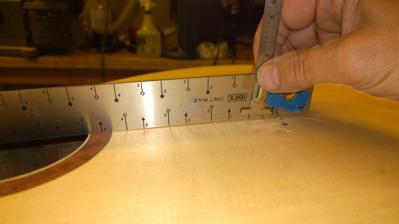
The carbon fiber on the top kept the top in the prefect shape. Absolutely no spring back. There was even a bit of vacuum when I put the top on the radius board that the top was glued up in. A straight edge on the fret board extension area of the top gave me the perfect 2.5 mm at the saddle that I am looking for.
When I fit the top to the rims it was easy to see that I made a little bit more longitudinal radius than I wanted. as the top needed to be pushed down about a mm at the blocks. It was hard to see this with the rims in the radius board as the neck block extension block the view. No big deal though. I carefully used a combination of a block plane and the radius board to take more off of the middle of the rims, until the top fit perfectly. It now sits on the rims requiring no pressure to hold it down. I also still have the correct body angle to match the required neck angle.
I need to route the rims for the back braces, a bit more cleanup and I can close the box.
- Nick Royle
- Wandoo
- Posts: 16
- Joined: Sun Oct 06, 2013 1:34 am
- Location: London, England
Re: Build thread for first Gore SS from the plans in the boo
It really is looking great, John! Can't wait to hear it!
Seeing this build makes my carbon fiber lattice guitar even more daunting to me! Still need to get a lot of stuff for it and still need to work out a good router table system for kerfing the lattice elements. If I can get started on it in a month or so I'll be lucky.
-
- Blackwood
- Posts: 552
- Joined: Mon Jan 21, 2013 2:59 am
- Location: Seattle
- Contact:
Re: Build thread for first Gore SS from the plans in the boo
Thanks Nick!
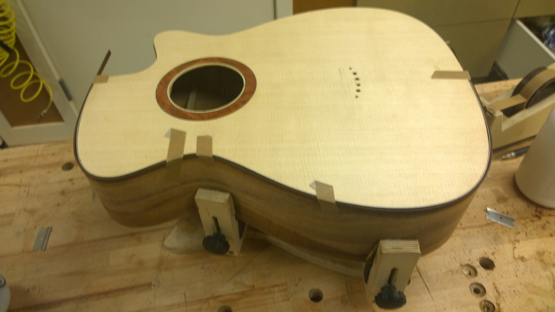
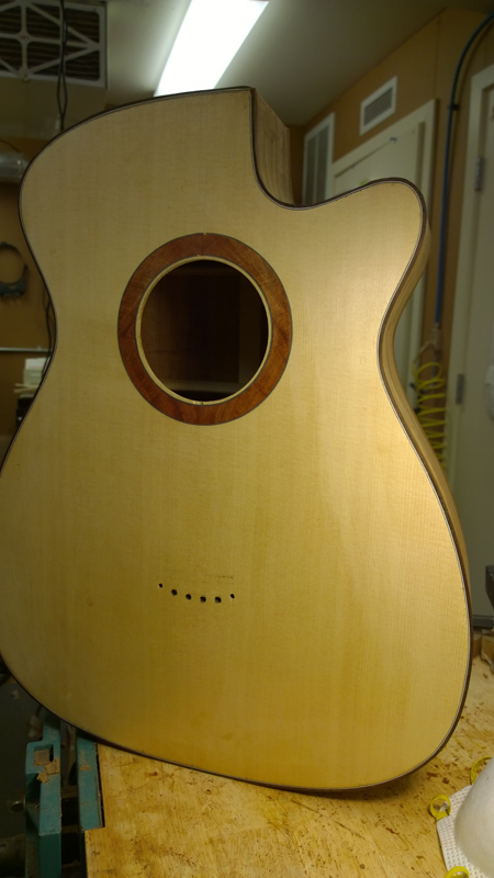
I closed the box yesterday and today. I did the back first and the top today. In each case I used my radius dish as a gluing caul and cam clamps. I do not have the picture gluing on the back but the guitar was in the mold with spreaders holding the guitar square to the mold. One the back was on the rims with the solid linings for the top no longer need a mold.
On to the bolt on bolt off neck ...
-
- Blackwood
- Posts: 552
- Joined: Mon Jan 21, 2013 2:59 am
- Location: Seattle
- Contact:
Re: Build thread for first Gore SS from the plans in the boo
Before I can really start working on the neck I needed to get the body bound and the tail wedge installed. The binding, head stock veneer and tail wedge are all cocobola. I have a thin BWB fiber purfling that matches the rosette that I am using for purfling.
Normally I install the end wedge before I close the box. This time I did not; I started to mark out the wedge before I routed for bindings but stopped when I realized that it would be hard to judge the depth and with no purfling on the back it would be easy to cut into the back. The book has it cut out after binding the guitar, using a set of steel rulers, a marking knife and a chisel to chisel out the waste and to miter the side purflings. I decided that I am not the good with cutting and ultimately I cut and chiseled out the wedge after I cut the binding rebate but before the bindings were glued in. (sorry not a full set of photos.)
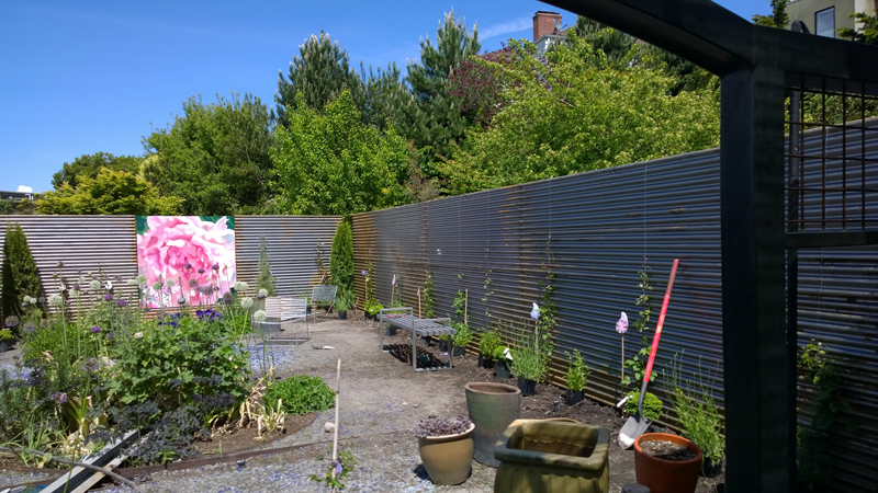
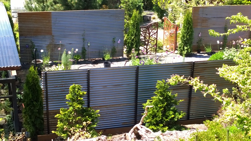
I had to slow down my shop work to build a pretty substantial corrugated steel fence for the hidden sculpture garden my wife designed, 40' by 21' by 7'; mounted on 2" sqr steel posts. The fence is bolted on 24 10" round by 2.5' concrete filled post holes. She offered to hire someone, but I imagined the estimate. The steel will be left to rust and for the most part in short order there will be a lot of clematis and other plants. I had the steel posts custom fabricated. I think I am finished for this season!
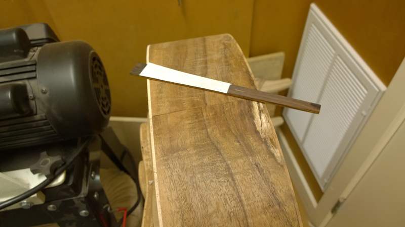
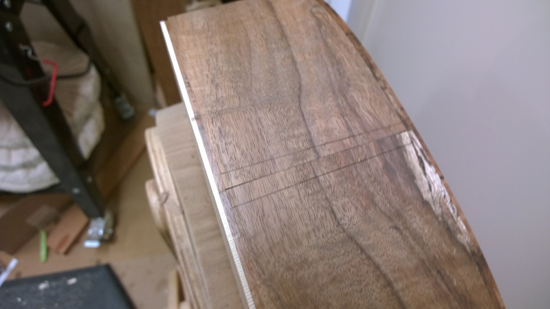
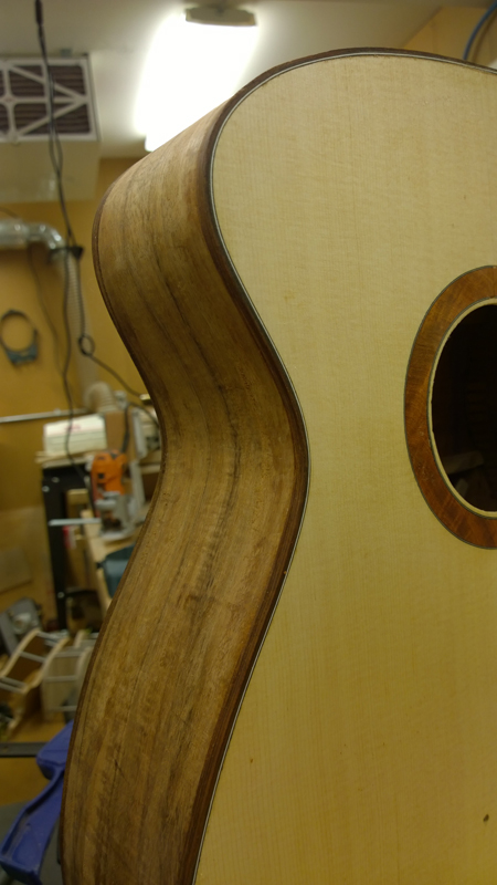
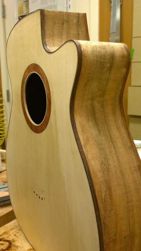
I finally got to bending the bindings for the cutaway one of the tasks that I have been nervous about. I did not have much luck my first try, so I sprayed the bindings with supersoft and waited a day. The super soft really helped, this cut away is really tight. On my previous cut away I softened the curves. Ultimately I did alright and got both bindings bent.
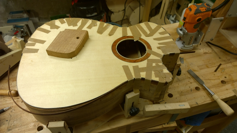
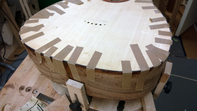
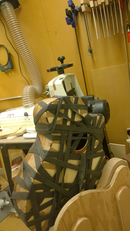
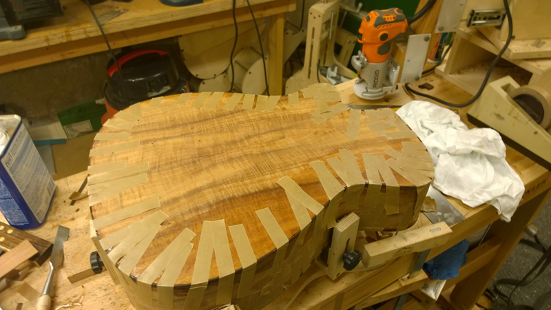
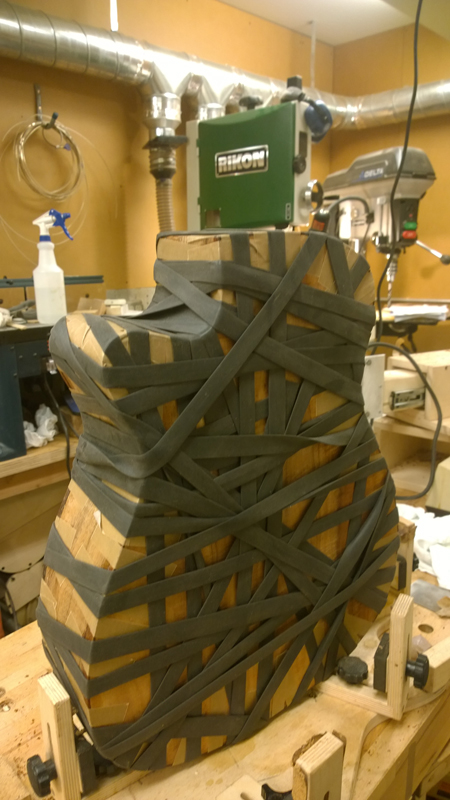
I used high tack fish glue to bind the guitar. I like the slow cure time as it allowed me to bind, first the entire top, following it with a tight wrap. I used a continuous strip for the entire top purfling. I waited a few hours fit and then glued on the back bindings followed with a complete wrap of the guitar with the long rubber strip.
-
- Blackwood
- Posts: 552
- Joined: Mon Jan 21, 2013 2:59 am
- Location: Seattle
- Contact:
Re: Build thread for first Gore SS from the plans in the boo
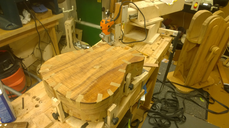
The binding turned out OK
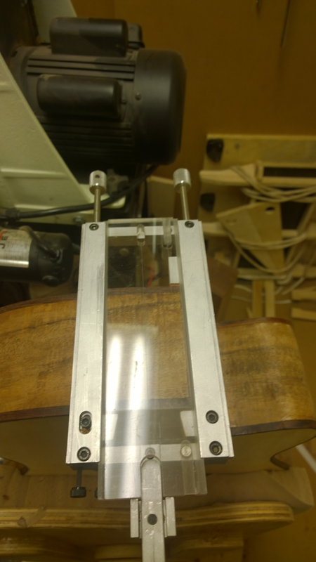
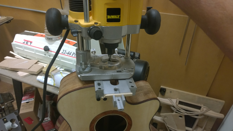
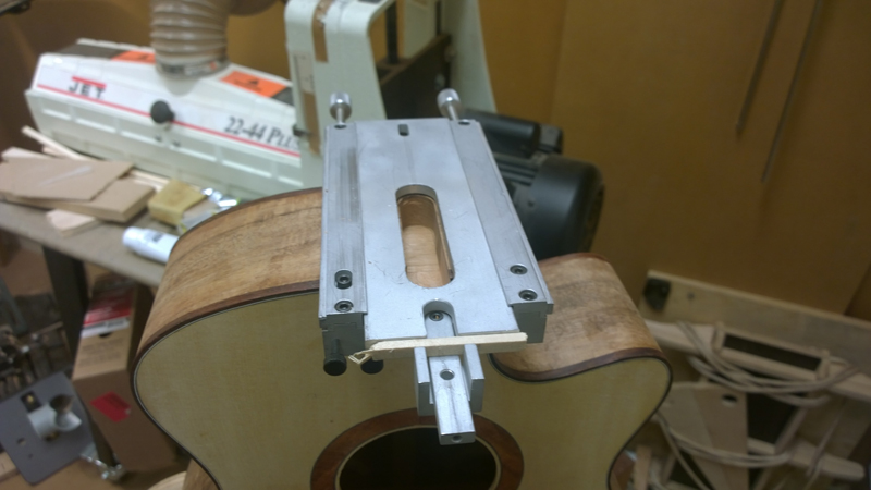
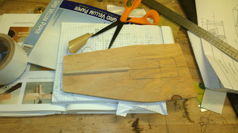
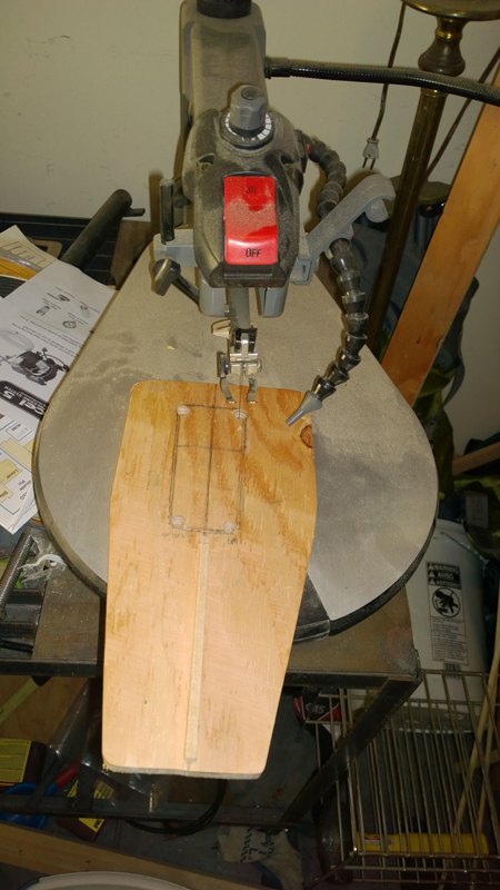
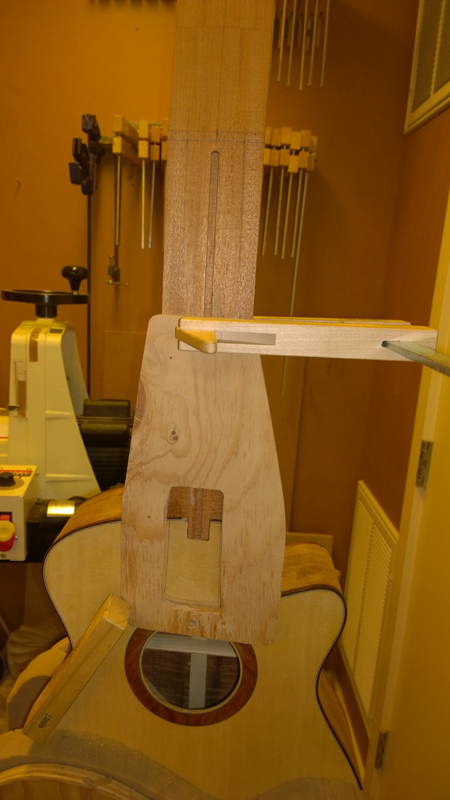
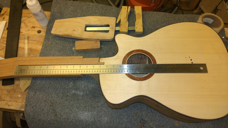
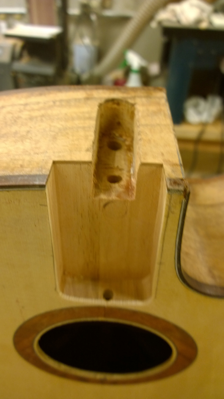
I deviated a bit from the book and I cut the mortise and the tenon using my luthier tool jig. I am use to a martin pattern with a flatter top rim profile. and I cut the mortise at a very slight angle. You will see below I had to do a bit of chisel work to get the neck to set properly. Another mistake is that I cut the bolt holes with my martin pattern which put the top side bolt for the tenon against the inside block extension. Live and learn . All and all it is all working out OK ...
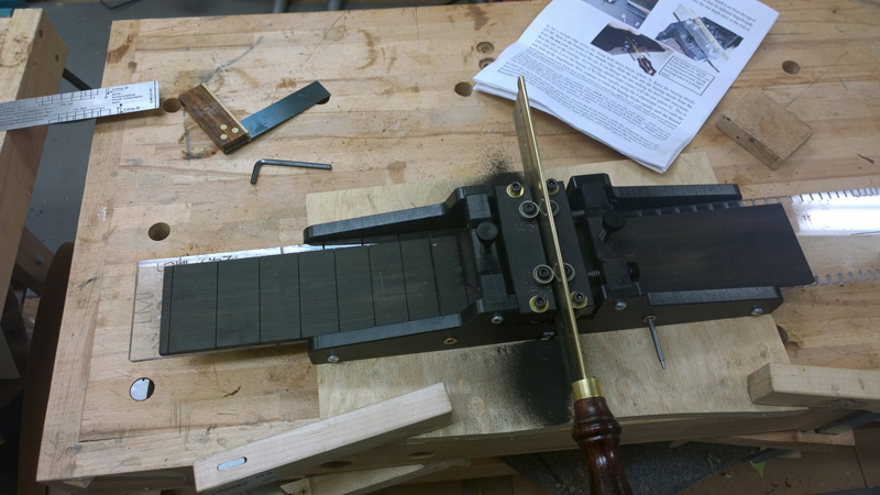
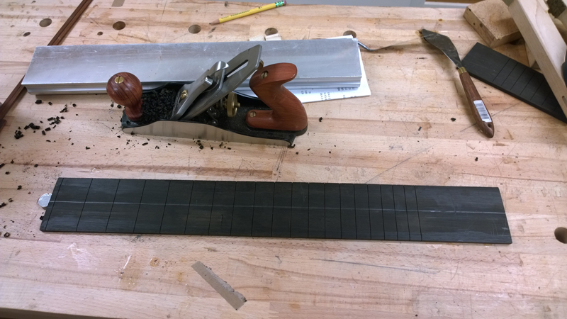
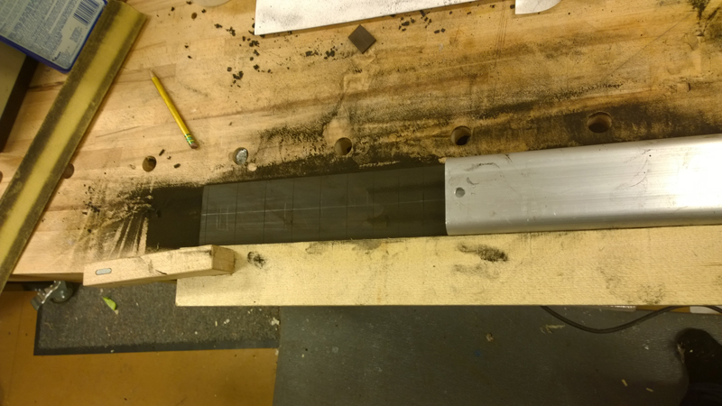
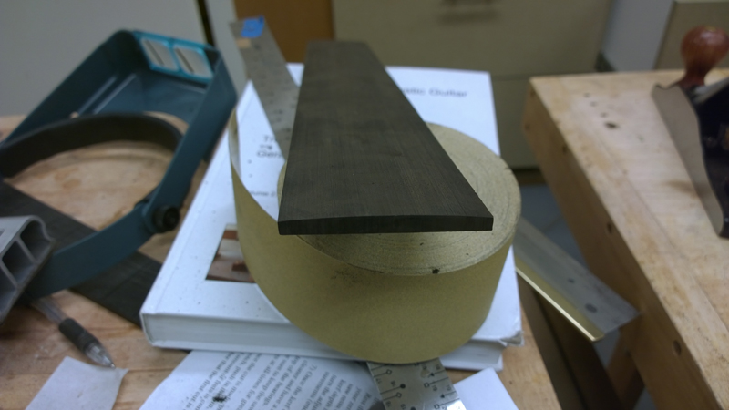
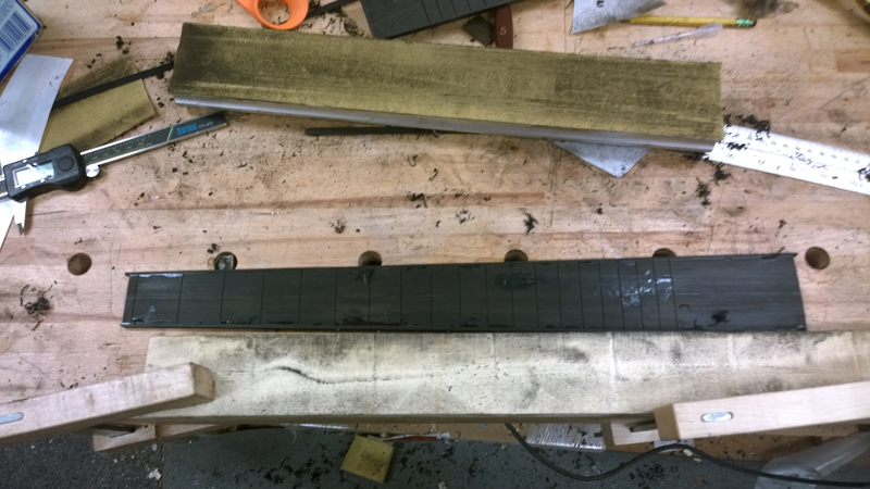
Made fret board
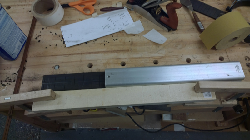
I roughed in radius with a plane
Note that I am using a guide to keep the sanding bar straight. This avoids over radiusing the edges by skewing the block.
I bound fret board with ebony bindings using CA.
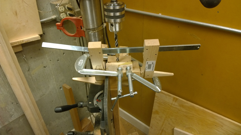
Used drill press to drill brass insert holes
Needed to do a bit of work on the mortise so that the fret board would be centered and flat to the body. That is why the mortise is rough in a few of the pictures. I think that my template was slightly rotated on the guitar. Once I adjusted the mortise the neck angle was OK.
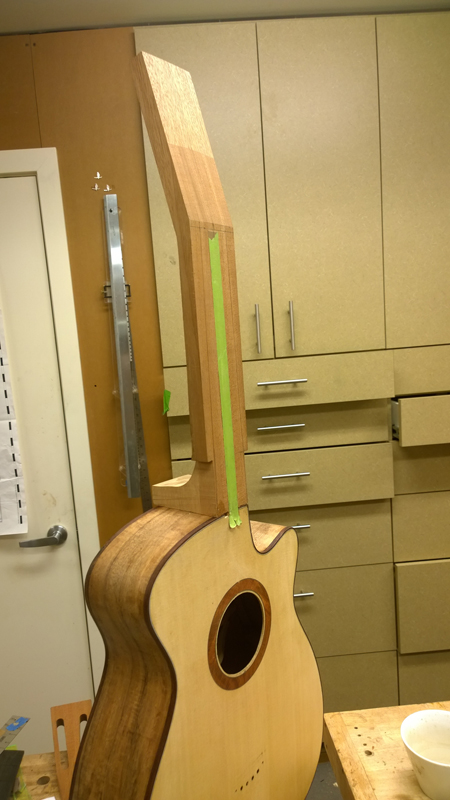
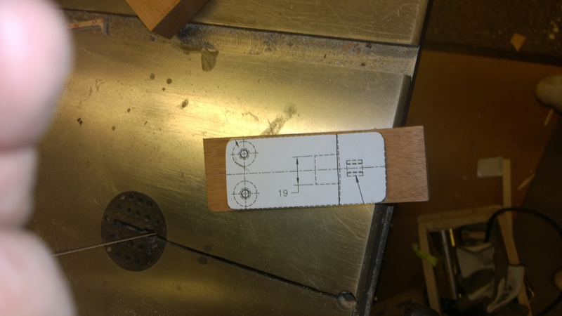
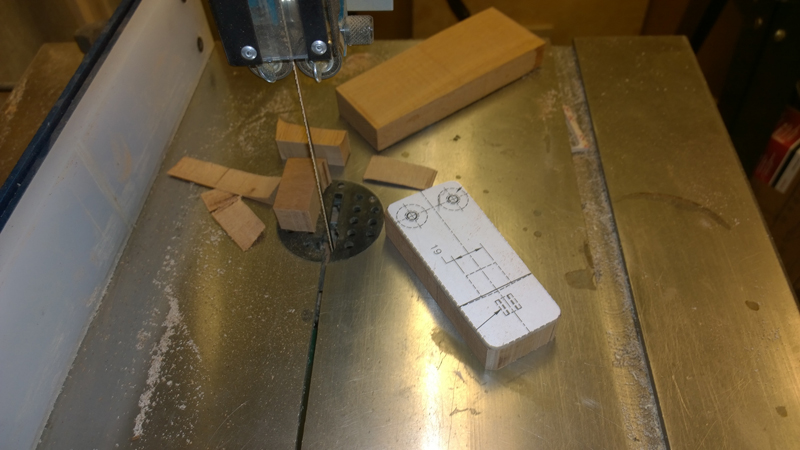
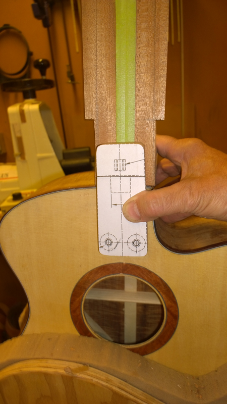
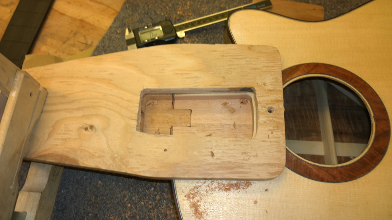
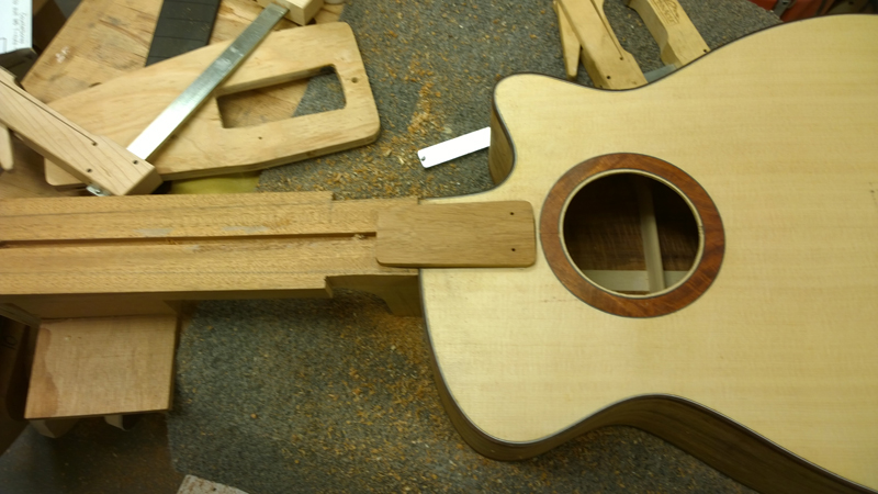
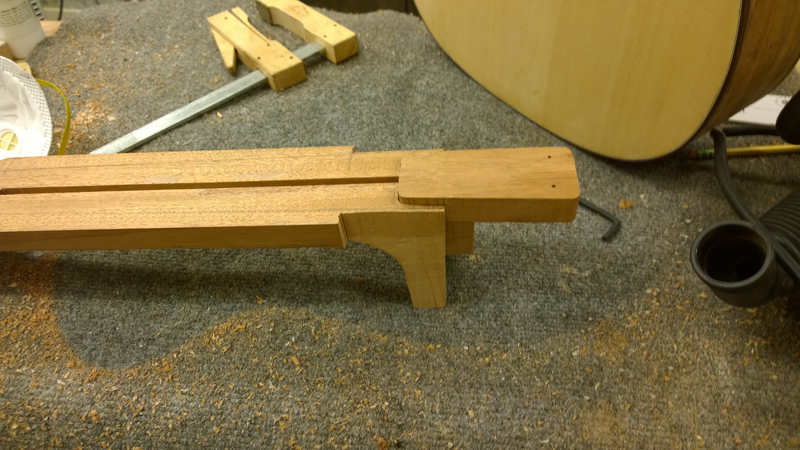
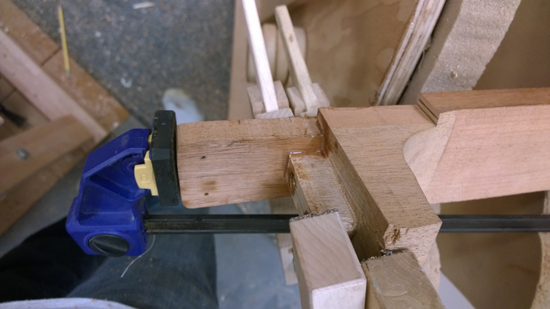
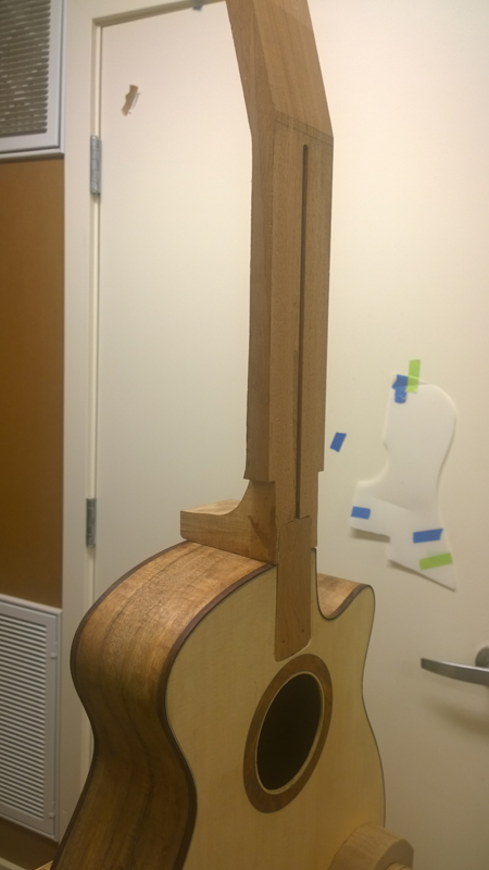
Now to the bolt on extension. I am going to let the pictures describe the process for the fret board extension as it was involved. Ultimately it sort of like an electric guitar mounting with a heel.
Before routing I double checked that I was centered and the angle was correct!
Note I am shifted to the bass farther than I wanted to be. Fortunately not too far.
My template was not perfect so I used structural epoxy for to glue on the extension.
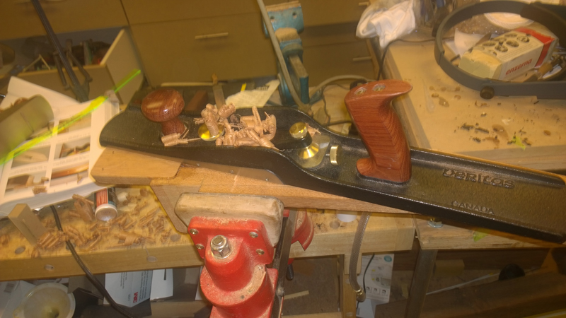
Planed the extension flat.
reestablished the channel for the truss rod.
I will install some t-nuts in the extension and bolt holes in the inside block. Then on to finishing the neck and head stock.
-
- Blackwood
- Posts: 552
- Joined: Mon Jan 21, 2013 2:59 am
- Location: Seattle
- Contact:
Re: Build thread for first Gore SS from the plans in the boo
Thanks John,
I started the head stock design to day ultimately making a mock up to test my layout. The book suggests a tuner layout that allows a straight run across the nut to the tuner post. Not having the break at the nut, while intonation by the nut will be the same, will have the feel of a longer string in terms of bends and the feel fretting them.
To properly layout the tuners I first needed to determine the string spacing at the nut, then I could layout the tuners so that they fit on the peg board and are positioned for the straight run.
I like to have my spaces relatively even as opposed to the string centers. In the past I have used the thickness of the strings to figure out the placement. The book had a simpler method that looks nearly as good. (I used it on my last guitar as well)
I first mark out E strings 3mm in on the bass side, 4mm in on the treble side I measure the distance in between. For this guitar is was 36.75 mm.
.
The strings are spaced .1mm farther apart as it moves from treble to bass. I mark the spaces A, B ,C, D, E, where A is between sting 1 & 2 and E is between 5& 6. So:
A = ((distance between strings 1 and 6) - 1 mm) / 5 | (36.75 mm - 1) / 5 = 7.15mm
B = A + .1mm = 7.25mm
C= A + .2mm = 7.35mm
D = A + .3mm = 7.45mm
E = A + .4mm = 7.55mm
Instead of measuring and laying out the spaces I calculated all the string positions starting with high E string as 0. This avoids accumulated layout errors.
High E = 0. B=7.15, G = 14.35, D = 21.74, A = 29.2, E = 36.75 mm
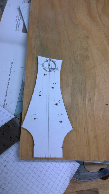
To design the shape. I started with my 1 3/4 nut width and use some of the base measurements for the curve to the nut from Trevor Gore's design. I drew in the string spacing and extended the lines up into the head stock. For each string I placed the center of the post hole 3 mm from the string lines away from the center . ( I made the mistake on my bass putting the posts on the string line.)
I used Tervor's plan in the book to space the tuners from the nut. With the tuner posts marked I made a dot up and out to mark where I wanted the knob shaft to hit the body.
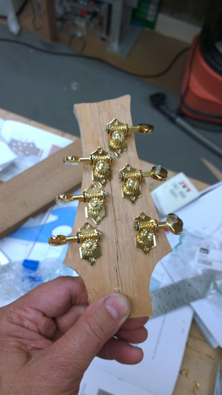
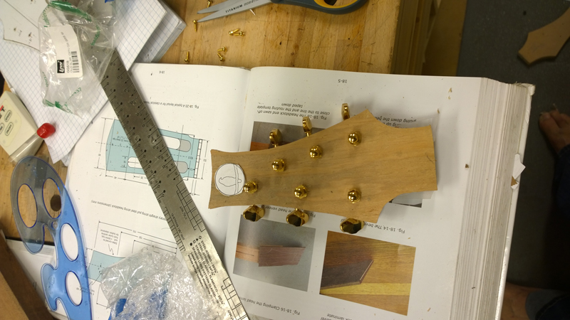
I drew in a rough placement for my logo and then used a french curve to hit my body intersection marks on each side and I went high enough to have room for the logo.
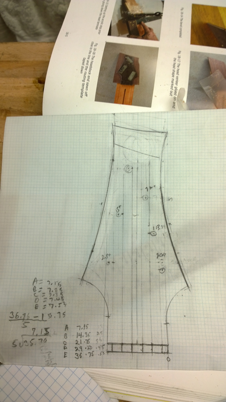
I copied my drawing and made a plastic template. Just to make sure the layout works I made a ply wood mark up.
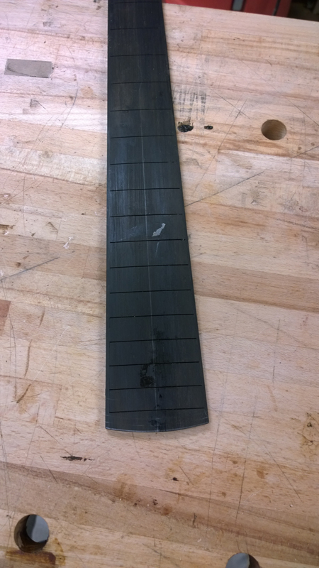
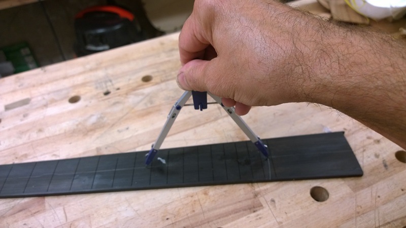
In the past I have been using paint cans and what not to transfer a curve to the bottom of the fret board. It finally dawned on me just to just use a compass. I have the center line so it is a lot easier.
More neck work this weekend.
I started the head stock design to day ultimately making a mock up to test my layout. The book suggests a tuner layout that allows a straight run across the nut to the tuner post. Not having the break at the nut, while intonation by the nut will be the same, will have the feel of a longer string in terms of bends and the feel fretting them.
To properly layout the tuners I first needed to determine the string spacing at the nut, then I could layout the tuners so that they fit on the peg board and are positioned for the straight run.
I like to have my spaces relatively even as opposed to the string centers. In the past I have used the thickness of the strings to figure out the placement. The book had a simpler method that looks nearly as good. (I used it on my last guitar as well)
I first mark out E strings 3mm in on the bass side, 4mm in on the treble side I measure the distance in between. For this guitar is was 36.75 mm.
.
The strings are spaced .1mm farther apart as it moves from treble to bass. I mark the spaces A, B ,C, D, E, where A is between sting 1 & 2 and E is between 5& 6. So:
A = ((distance between strings 1 and 6) - 1 mm) / 5 | (36.75 mm - 1) / 5 = 7.15mm
B = A + .1mm = 7.25mm
C= A + .2mm = 7.35mm
D = A + .3mm = 7.45mm
E = A + .4mm = 7.55mm
Instead of measuring and laying out the spaces I calculated all the string positions starting with high E string as 0. This avoids accumulated layout errors.
High E = 0. B=7.15, G = 14.35, D = 21.74, A = 29.2, E = 36.75 mm
To design the shape. I started with my 1 3/4 nut width and use some of the base measurements for the curve to the nut from Trevor Gore's design. I drew in the string spacing and extended the lines up into the head stock. For each string I placed the center of the post hole 3 mm from the string lines away from the center . ( I made the mistake on my bass putting the posts on the string line.)
I used Tervor's plan in the book to space the tuners from the nut. With the tuner posts marked I made a dot up and out to mark where I wanted the knob shaft to hit the body.
I drew in a rough placement for my logo and then used a french curve to hit my body intersection marks on each side and I went high enough to have room for the logo.
I copied my drawing and made a plastic template. Just to make sure the layout works I made a ply wood mark up.
In the past I have been using paint cans and what not to transfer a curve to the bottom of the fret board. It finally dawned on me just to just use a compass. I have the center line so it is a lot easier.
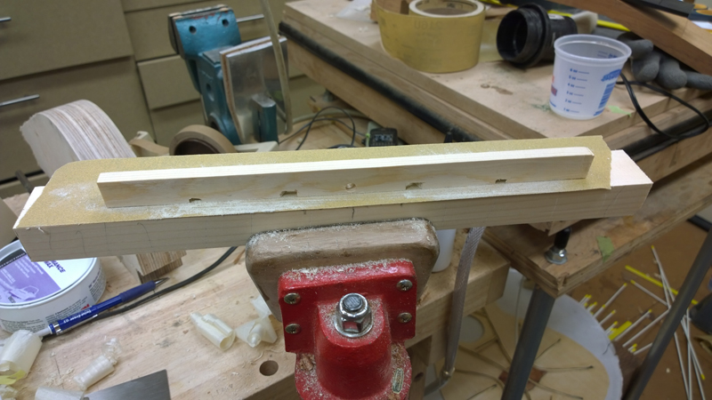
More neck work this weekend.
Who is online
Users browsing this forum: No registered users and 11 guests